

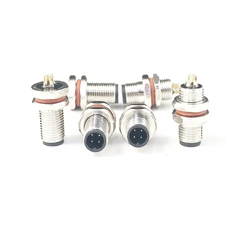
A panel-mounted connector is part of the enclosure design, not a separate purchasing detail. Its location affects cable routing, wrench access, internal harness length, label visibility, and the way a machine is serviced. The most reliable plans start by treating the connector as a boundary component with mechanical and electrical responsibilities on both sides of the panel. That approach prevents the cutout from being finalized before the mating and service requirements are understood.
Begin with an installation sketch rather than a part number. The sketch should show the panel face, material and thickness, cutout region, nearby components, outside cable direction, inside harness path, and the tools needed during assembly. Include the available clearance around the coupling area. A connector may fit through the panel while still being difficult to tighten, disconnect, or inspect once brackets, guards, and labels are in place.
The external environment should be evaluated where the interface is actually installed. A panel on the top of a cabinet can experience runoff or cleaning differently from one on a protected sidewall. A connection under a machine may face debris and limited access. These details influence the desired orientation, the way cable weight is supported, and the maintenance instructions supplied with the equipment. They should be part of the design record, not assumptions held only by an installer.
Engineers comparing enclosure interfaces can review waterproof circular connectors to frame choices among cable-end, panel-mount, and flange-style configurations. The useful question is not which outline looks most familiar, but which arrangement preserves sealing, access, and cable control in the finished enclosure.
Internal routing deserves equal attention. The short distance between a panel connector and a terminal block can still produce an awkward harness if the cable must cross a door hinge, a heat source, or a sharp edge. Record the connector orientation and expected cable exit before locking the internal layout. This gives harness designers a defined endpoint and helps avoid excessive twisting or unsupported cable sections after installation.
Serviceability often changes the preferred location. A field technician may need to disconnect one cable without disturbing adjacent circuits, while an assembly technician may need room to hold a backing nut or use a torque tool. Identify who will access the connection, from which side of the panel, and at what stage of the machine lifecycle. A layout optimized solely for initial assembly can be expensive to maintain later.
The procurement package should translate these needs into unambiguous questions: mating counterpart, contact count, coding if relevant, panel fit, installation direction, cable preparation, and the requested sample configuration. Photos of a mock-up can be valuable because they reveal clearance problems that are not obvious in a bill of materials. The goal is a like-for-like comparison, rather than a list of connector families with different mounting assumptions.
Panel interfaces work best when the mechanical layout and electrical connection are approved together. By documenting the cutout, cable route, mating access, and expected exposure early, a project team can select components with fewer late revisions. The final review should use a physical or digital installation representation and confirm that the mated connection remains practical for assembly, inspection, and routine replacement. A useful final activity is a panel-access walk-through using the expected tools and cable assembly. The review can reveal a connector hidden by a machine frame, a coupling that conflicts with a door swing, or an internal harness that cannot be routed without a tight turn. Resolving those details in a mock-up is usually easier than modifying a finished panel, harness, or enclosure drawing after production has begun. The sign-off should identify the actual installation orientation and note any assembly aids required at the panel station.
Submit guest articles that reach decision-makers, influencers, and professionals. Yarabook offers a trusted platform for quality content, strong backlinks, and SEO-driven visibility. Pay. Publish. Promote.